The Tree Nurturing System (TNS™) provides kerb-line retention and storage beneath street trees. Maintenance is the question every technical review of the system ends on, and it deserves a straight answer. The short version: debris stays on the surface where a sweeper takes it. Nothing wears: the tray and the filter clog slowly by design and lift out. They are expected to run far longer between services than a side-entry pit takes to fill with sediment, debris and organic matter. A blocked node leaves the street open, with failure of a whole run at once a remote case. In a true flood the road reserve conveys floodwater downhill, as it always has, along the relief path we design in.
The system is routinely mis-read as a tank with a tree on top. It is the other way round, and almost every maintenance question answers itself once the arrangement is clear. The full water path, step by step, is on How it works.
On frequent rainfall – the great majority of events – very little storage is called on. Water passes through the manifold into the media and soil cells and keeps moving down, with the tanks barely engaged.
On larger events the soil cells may saturate, and only then do the tanks take up the volume the profile can no longer accept. The relief line engages later still, and only once storage and substrate are both satisfied. On an ordinary event it does not engage at all.
Meanwhile the tree transpires and the surrounding profile draws moisture. The store is drawn down slowly and continuously between events, not held. What sits under the street most of the year is moist media and moist soil – not water.
Lined tanks are a variant, not the default. Tanks are unlined unless there is a reason – retention for harvesting and reuse, or a site where infiltration to the underlying profile is not permitted. A lined tank, chosen as a deliberate design election, is the only configuration in which the system holds standing water for a sustained period.
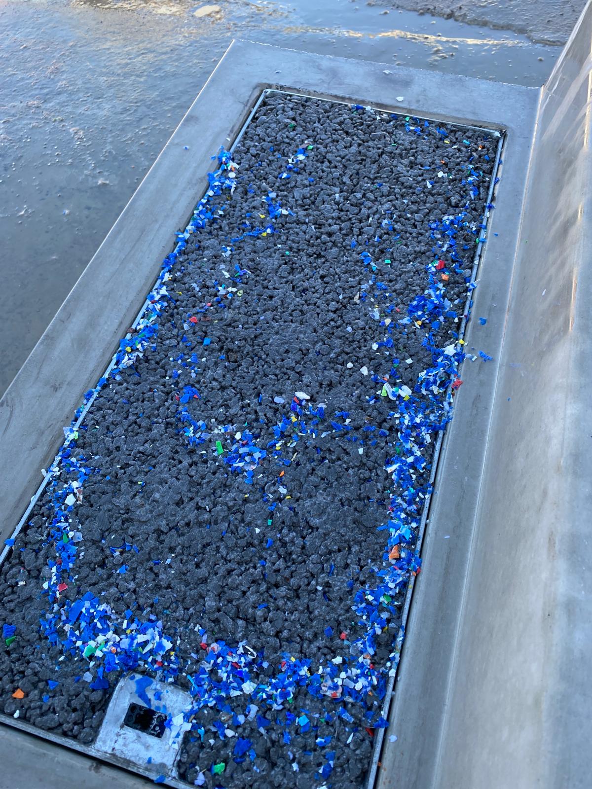
Water enters the system through a closed kerb face, which holds back the debris that runoff carries and leaves it on the surface for the street sweeper.
The EnviroKerb Tray Inlet (ETI) is a sealed, removable tray, while the EnviroKerb® unit admits water through a porous concrete body. Gross pollutants and coarse material stay at the kerb line, on the surface, and never enter the subsurface.
Debris on the surface is collected by a machine already scheduled on that street. Debris inside a subsurface structure needs a crew, an opening operation and a confined-space consideration.
The closed kerb face is what moves the dominant maintenance action from subsurface work into surface work. Everything else in the regime – the consumable filter, the removable tray, the modular unit – deals only with what gets past that first line.
The answer to “What is your redundancy provision, short of block?” accepts that any system can block. Redundancy works at three scales, of which authorities ask about the third.
Because each node serves its own micro-catchment, water a blocked node cannot take continues along the kerb line to the next node. No single point of entry exists whose failure would fail the run.
Above the design storm, the system is meant to be exceeded. Frequent events are retained in the profile; larger events pass to the designed overflow route once storage and substrate are satisfied. Because the nodes are distributed, that overflow is never concentrated at a single point.
For the case where every unit in a run is out of service at once, a surface relief path is provided as part of the design. The provision is specific to each site, sized so the corridor has somewhere to send water if the whole system were unavailable. That case is already remote with several nodes in a run. In a true flood the road reserve conveys floodwater downhill, as road reserves always have.
We do not argue against this requirement. A relief provision that never operates costs a fraction of the conveyance network it displaces, and it turns an unresolvable argument about failure probability into a bounded design item. We would rather include the relief provision than win the argument about it.
Starting from the correct engineering assumption that everything breaks, the question is whether getting to the broken thing needs a specialist.
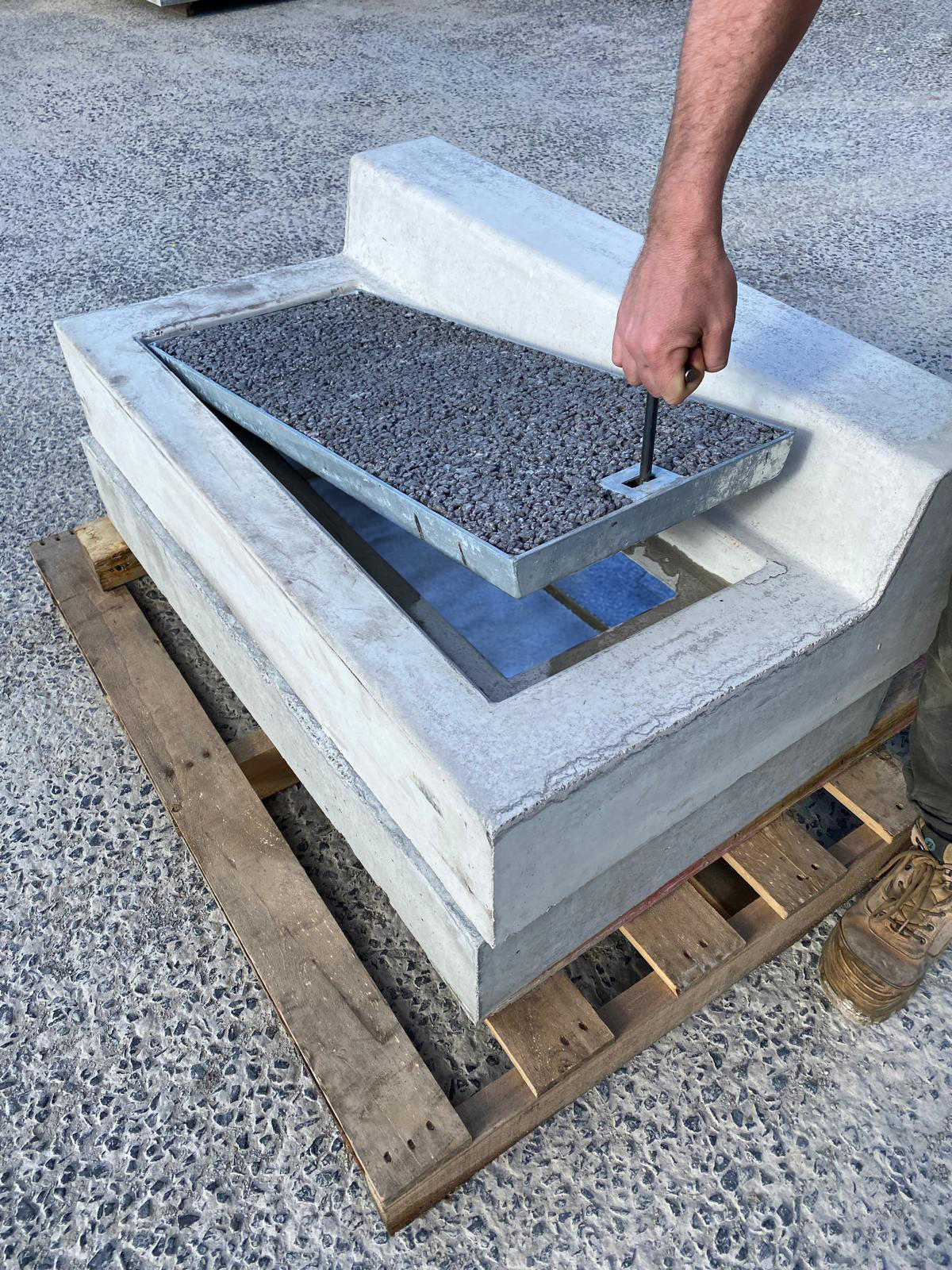
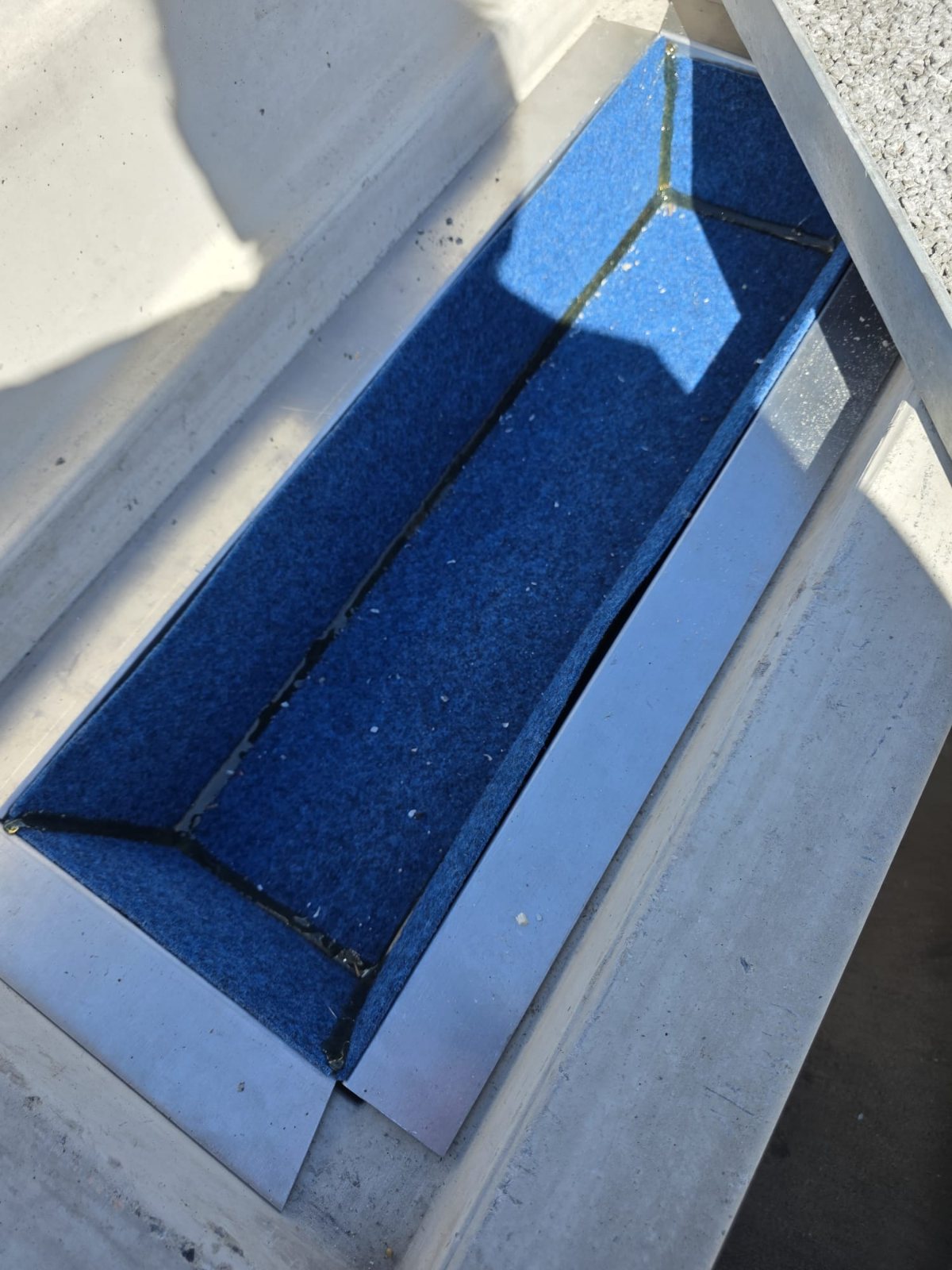
The ETI is a removable galvanised tray, Class D rated and fully trafficable, that lifts out on a locking arrangement without excavation or proprietary tooling.
The ARI Water Filter beneath the tray consumes itself protecting the void structure below. It is replaced by removal, not cleaned in place – a part swap, not a procedure.
Where a continuous porous kerb run is renewed as a length, a spaced node is lifted and replaced individually. The worst case at any single point is the replacement of one unit.
Installations can be detailed with inspection access on request for camera inspection of the manifold and storage – giving asset teams a direct view of condition and root interaction over time, in place of an inference from sensor data.
On private land the obligation belongs to the Owners Corporation or landholder. In a road reserve it belongs to the authority, as it does for any drainage asset. Ownership is settled at handover, with no residual obligation to BGI. The owner can contract the servicing out like any drainage function, in the way Owners Corporation installations already run under contract with a company that carries the plant.
A maintenance management plan accompanies every installation and is provided with the approval documentation, whatever pathway the project takes. It is site-specific, not a generic manual – the regime is built from the project's own catchment, sweeping regime and node arrangement. Asset teams see the servicing regime and the deviation thresholds before the asset is handed over, not after.
Nothing proprietary is required to service it. Every maintenance tier uses plant a council or contractor already owns and operates – a vacuum sweeper, a pressure unit, small plant for a module lift. One vehicle can carry the lot: a vacuum sweeper truck with a pressure unit and spare trays on board services a whole run in a single pass. Servicing with existing plant was a design constraint from the outset. A maintenance regime that depends on a manufacturer's service contract does not resolve a liability; it transfers one and adds a supplier dependency on top.
Gross pollutant traps, sediment basins and the vacuum-truck cycle that serves them exist because the network concentrates and conveys. Retain runoff at source and the load reaching them falls with it.
Establishment watering of street trees is a recurring, labour-intensive cost with a poor success rate. Passive irrigation at every frequent rainfall replaces the truck run.
A tree that fails in a compacted pit is replaced, and charged to the same budget. Root-zone water, oxygen and soil volume are the cheapest tree-asset insurance available.
The dominant action is vacuum street sweeping – already scheduled on the street for reasons unrelated to drainage.
Entering a stormwater pit is confined-space work under the WHS Regulations. A clean is not a task, it is an operation:
Because debris never enters the subsurface, the dominant action is the vacuum sweeper run the street already receives. The tiers above it – a tray lift, a filter swap, a pressure wash – are one-person surface tasks, with no confined-space entry, eductor truck or extraction load to dispose of.
The comparison rests on a category difference in what the work is, with no invented percentage behind it.
Each Matter SensAI unit sits behind the water ramp of the kerb unit it serves, configured with a baseline intake curve calibrated to that unit unblocked. A fall in measured intake below that curve raises an inspection notification on a tablet or a phone, naming the location and the indicated action before a blockage forms.
The more useful property of the monitoring is spatial, because it compares each node with its neighbours. One node deviating while its neighbours hold baseline points to a local cause, such as a bag over the tray, dumped material or a damaged unit. Upstream, subject and downstream deviating together points to a street-scale condition. That cross-reference is the difference between lifting every unit in a run to find the blocked one, and being told which one it is.
| Deviation from baseline | Action | Equipment | Crew |
|---|---|---|---|
| Minor | Vacuum street sweeping through the zone | Council sweeper | Existing sweeper run |
| Moderate | Lift and pressure-wash the ETI tray | Pressure unit | One |
| Significant | Replace the ETI tray insert or ARI Water Filter | Replacement consumable | One |
| Major | Pressure-wash the EnviroKerb® unit | Pressure unit | One |
| Critical | Lift out and replace the EnviroKerb® unit | Replacement module, small plant | Two plus plant |
Where this framework stands. The tiers are calibrated from the observed behaviour of the kerb units, not from a field-validated fault-classification model. Threshold calibration and the deviation-to-cause mapping need instrumented field data from a pilot that is part of the research programme below.
In development – AI camera verification. The Matter team is developing AI-enabled camera technology, co-located with the sensor units, to estimate the rate, spread width and depth of water in the kerb and channel. Once the cameras leave development, their estimates cross-referenced against sensor data would add a redundant verification layer.
Technology partner. BGI integrates the SensAI radar-and-AI units from Matter (watermatters.ai), whose current sensing hardware also includes FloodScan, for real-time stormwater and flood monitoring.
"How often does it need servicing" assumes a scheduled inspection round, with every unit checked so the blocked one is found, which is a model this system does not follow. Each node is monitored against its own baseline, and the measured deviation flags which node needs attention and how urgently. Servicing is by exception, not by schedule, which makes the regime proactive. What varies from street to street is how often flags occur, and three things drive it.
Sediment comes from land use, tree litter, traffic and construction activity upstream. This dominates everything else, and loss of capacity tracks cumulative load rather than elapsed time.
Fine-particle capture is what matters, and sweeper type changes it materially: regenerative air and vacuum plant lift the fines that a mechanical broom pushes down into the voids. The same street on different plant implies a different node interval. Vacuum or regenerative air plant only – a rotary broom pushes fines down into the voids, and the manufacturer's schedule excludes it.
Closer spacing puts less load on each node and lengthens the interval between services, at a capital cost that rises as spacing closes. It is a dial, and we set it per street.
The only field test a crew needs. The test, taken straight from the manufacturer's maintenance schedule, is to tip a bucket of water in: water that disappears means the unit is working; water that drains slowly means bringing the next clean forward.
Hold a few spare trays. A flagged tray is then exchanged on the spot in minutes and flushed back at the depot at a convenient time – no traffic management, no wet work in the road reserve. The manufacturer rates this the single most effective way to keep maintenance cost down.
What you get, per project. Each project gets an indicative service expectation derived from your catchment and sweeping regime, a baseline calibrated at commissioning, and thereafter a measured record from the monitoring data in place of a modelled one. The service estimate improves the longer the asset runs and the more monitoring data it builds up.
Three findings hold consistently across the published permeable pavement research cited below. Capacity declines along an exponential curve with cumulative sediment loading, with most of the loss happening early. Clogging progresses from the upgradient edge of a permeable surface toward the downgradient edge, which makes a continuous run fail at one end and get renewed as a length. Restoration is partial and depends on method: combined pressure washing with vacuum suction restores a substantial share, while surface vacuuming alone often does not. Where fines have migrated below the surface, no surface method works.
None of that is a reason to avoid porous infrastructure. It is a reason to put the porous element where accumulation is concentrated at reachable points. In that arrangement the part that consumes itself is a cheap consumable, with the element that eventually cannot be restored built as a module that lifts out.
On the TNS™, a clogged kerb unit is a component that is lifted out and replaced where it sits. The ETI tray lifts out on its standard Gatic locator, with a spare tray going in on the same visit and no traffic management needed.
An EnviroKerb® unit that a pressure wash and a vacuum truck can no longer bring back is lifted out whole on its cast-in threaded sleeves. The replacement drops into the same position between kerb sections that stay where they are, with no saw cutting or breaking out along the street. The worst case at any single point is one precast unit of about 200 kg, lifted and replaced with the small plant a council already runs.
Porous surfacing has been on United States highways since the 1950s, and the early performance problems that soured some road authorities in the 1970s were materials problems since engineered out. The porous asphalt car park at Walden Pond, laid in 1977, is still in service after more than forty-five years without full repaving.
But an urban street is not a highway. Part of why highway porous surfacing stays open is that high-speed traffic scours fines from the voids – which is why it is expressly not recommended for low-speed pavements. Australian streets are low-speed, high-deposition environments that get the sediment without the self-cleaning.
The whole argument for the kerb line follows: put the porous element where it can be lifted, serviced and replaced, and keep it off a trafficked surface where it cannot be.
The relief provision is specific to each site, with the surface relief path designed in from the start in whatever form the corridor allows. Although simultaneous failure is remote with several nodes in a run, we size the relief path anyway in preference to arguing probability. In an extreme flood the road reserve conveys floodwater downhill, as it always has.
These units admit water through a void structure, a sealed removable tray and a porous concrete kerb body, which keeps debris on the surface where a sweeper collects it. Gross pollutants stay at the kerb line and never reach the subsurface structure.
Three parts give access: the tray lifts out on a locking arrangement; the filter beneath it is a consumable that is swapped, not cleaned; and a whole module can be lifted and replaced individually. Installations can be detailed with inspection access on request for camera inspection of the subsurface.
A completely clogged unit is lifted out and replaced by a new one in the same position, with the kerb line either side left as it is. Each unit has its own lifting point – a standard Gatic locator on the ETI tray and cast-in threaded sleeves on the EnviroKerb® unit.
The obligation belongs to whoever owns the land, as with any drainage asset, whether that is an Owners Corporation, a landholder or an authority. The node is designed to be serviced with plant that owner already operates. The work itself is routinely contracted out – Owners Corporation installations are already serviced this way, under contract by a maintenance company with the plant.
No contract with BGI is needed, although we provide the regime, the thresholds and crew training. Owners who would rather not self-perform contract the regime out in the way Owners Corporations already do. The asset carries no ongoing obligation to BGI once it is handed over.
Storage is distributed, with each node holding its own manifold, tanks and soil cells for its own micro-catchment and no central chamber. On most rainfall the water is not sitting in the tanks at all; it is moving down through the filter media and structural soil cells toward the root zone.
In the default arrangement the tanks are unlined and hold no sustained standing water to go anaerobic, filling on a large event and draining down through the profile afterwards. Where tanks are deliberately lined for harvesting or reuse, water is retained and low dissolved oxygen should be expected; that condition is engineered on purpose in stormwater biofilters to drive denitrification. In either arrangement the root zone is not the saturated zone, because water arrives oxygenated from above and filters down through the root mass.
What is left is moisture in the profile, held in the media and soil in place of litres in a tank. Water held in media and soil is drawn down at transpiration rates, not conveyance rates, and moves slowly downward and laterally, perching where the geology allows. Available moisture stays in the profile with no obvious volume to see, on the same principle that lets rehydrated rural landscapes carry through dry cycles.
The system has no calendar interval to defend, because each node is monitored against its own baseline. Servicing happens by exception and not by schedule, with the measured deviation flagging which node needs attention and how urgently. How often flags occur depends on sediment supply at the kerb line and on your sweeping regime.
The maintenance substitutes for existing work: source retention reduces the load reaching end-of-line assets; passive irrigation displaces manual watering; and the dominant action is street sweeping already scheduled for other reasons. A five-year whole-of-life costing against the displaced asset comes with every installation.
The maintenance plan arrives before handover, provided with the approval documentation whatever pathway the project takes.
The positions on this page rest on published permeable pavement, biofiltration and smart stormwater research, set out with full citations in the technical paper below.
Where the literature stops is the specific question of how to space, monitor and renew a discretised porous interface at the kerb line at least cost. We are quantifying that as an industry partner of the ARC Training Centre for Climate-Resilient Water, through service-spacing optimisation, restoration efficiency across repeated cycles, and sensor threshold calibration against observed obstructions. The Centre is a national centre led by The University of Queensland with Griffith University and the University of Technology Sydney. The TNS™ itself has not been assessed by the ARC Training Centre.
The practical consequence for an asset owner is straightforward: the service interval you are given is measured on instrumented assets, not assumed, and it improves with every season of data.
Clogging, serviceability and sensor-driven operation and maintenance (O&M) in kerb-line source control is fully referenced, with every claim labelled by evidence status: established, BGI position or open question. The labels show the assessing engineer exactly what is literature and what is our judgement.
We email the paper in place of hosting it, which lets us see who is assessing what and follow up with the detail that matters to your project.
The paper is free to request and share intact, with reproduction, adaptation and derivative use excluded under the terms.